
Glass Facades
Glass Fin Stability Systems: Wind Bracing Design for Ahmedabad Commercial Lobbies
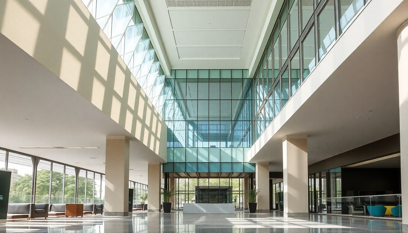
Glass fin stability systems provide the lateral bracing necessary to support large frameless glass walls in commercial lobbies, transforming architectural vision into structural reality. In Ahmedabad's climate—where wind speeds can reach 47 m/s during severe weather events and ambient temperatures swing between 15°C and 45°C—proper fin design becomes critical to prevent catastrophic failure while maintaining the aesthetic transparency that defines modern commercial architecture. This engineering guide walks through the complete design process, from finite element analysis to connection detailing, ensuring your glass lobby walls meet both safety standards and architectural expectations.
Understanding Glass Fin Wall System Fundamentals
Glass fin systems consist of vertical glass panels that extend perpendicular to the primary glazing, acting as structural ribs that resist lateral wind loads and transfer them to the building structure. Unlike traditional framed systems, these fins allow uninterrupted transparency while providing the necessary stiffness to stabilize large glass expanses. The primary glazing connects to the fins through specialized point-fixed hardware or continuous structural silicone joints, creating a composite system where both elements work together to resist applied loads.
The structural efficiency of fin systems depends on three critical factors: fin depth, glass thickness, and connection rigidity. Deeper fins provide greater moment resistance, while thicker glass increases both strength and stiffness. The connection between fin and primary glazing must transfer shear forces without inducing excessive stress concentrations that could initiate crack propagation. In Ahmedabad's commercial lobbies, where floor-to-ceiling heights often exceed 4.5 meters, these parameters require careful optimization to balance structural performance against material costs.
Material Selection for High-Temperature Environments
Ahmedabad's peak summer temperatures demand heat-strengthened or fully tempered glass for both fins and primary glazing. Annealed glass lacks the thermal stress resistance needed for direct solar exposure in this climate. Fins typically use 12mm to 19mm fully tempered glass, while primary glazing may incorporate laminated units for safety. The lamination interlayer—usually PVB or ionoplast—must maintain structural integrity at temperatures up to 50°C, which represents the realistic glass surface temperature under direct afternoon sun exposure.
Wind Load Calculations for Ahmedabad Climate Zones
Accurate wind load determination forms the foundation of safe fin system design. IS 875 Part 3 classifies Ahmedabad in wind zone II, with a basic wind speed of 39 m/s for general terrain. However, commercial lobbies in urban centers experience modified wind pressures due to surrounding building heights and terrain roughness. The design wind pressure equation accounts for risk coefficient, terrain factor, topography factor, and importance factor, typically yielding pressures between 1.2 to 2.0 kPa for mid-rise commercial buildings.
Dynamic effects become significant for flexible glass systems with natural frequencies below 1 Hz. The gust factor method in IS 875 provides a simplified approach for most lobby applications, but buildings exceeding 30 meters or those with unusual geometries may require wind tunnel testing. Local wind patterns in Ahmedabad, particularly during monsoon season from June through September, can create suction pressures on leeward facades that exceed positive pressure magnitudes, making bidirectional design essential.
- Calculate basic wind pressure using IS 875 Part 3 methodology
- Apply appropriate risk and terrain modification factors
- Consider both positive and negative pressure coefficients
- Account for corner and edge zone pressure amplification
- Include thermal expansion effects in connection design
Finite Element Analysis Methods for Glass Fin Systems
Finite element analysis provides the most accurate method for predicting stress distributions and deflections in complex glass assemblies. Commercial FEA software packages model glass as an elastic, isotropic material with a Young's modulus of 70 GPa and Poisson's ratio of 0.23. The analysis must incorporate geometric nonlinearity for systems where deflections exceed 1/100th of the fin depth, as large displacements alter the load path and stress distribution significantly.
Mesh refinement around connection points requires particular attention, as these regions experience the highest stress gradients. A typical analysis uses 25mm to 50mm shell elements for general areas, refining to 5mm to 10mm elements within 150mm of hardware locations. The connection hardware itself can be modeled as rigid links, spring elements with measured stiffness values, or detailed solid elements depending on the required accuracy level. Validation against physical testing data ensures the model accurately represents real-world behavior.
Stress Evaluation and Safety Factors
Allowable stress limits for tempered glass depend on load duration and surface condition. For wind loads with durations under three seconds, IS 2553 permits design stresses up to 28 MPa for tempered glass. However, conservative practice limits tensile stresses to 20-24 MPa to account for edge quality variations and installation-induced flaws. The FEA output requires careful interpretation—principal tensile stress governs failure initiation, and maximum values typically occur at connection points or along unsupported edges.
Safety factors in glass design differ from conventional structural materials due to glass's brittle failure mode. A minimum factor of 2.5 against calculated ultimate strength provides adequate reliability for commercial applications. This factor accounts for material strength variations, surface damage during handling, and analysis uncertainties. Professional firms like Sky Earth Architects incorporate these safety considerations into their lobby designs, ensuring long-term performance under actual service conditions.
Deflection Limits and Serviceability Criteria
Deflection control ensures visual acceptability and prevents damage to secondary elements. Industry practice limits glass deflection to L/60 under design wind loads, where L represents the unsupported span. For a 3-meter-high lobby panel, this translates to a maximum 50mm deflection. More stringent limits of L/100 to L/125 apply where glass contacts rigid architectural elements or where visual distortion concerns exist. The deflection calculation must include both fin bending and primary glazing deformation, as the system acts compositely.
Connection slip represents an often-overlooked deflection component. Point-fixed hardware can experience 2-5mm of movement under ultimate loads due to bolt bearing, gasket compression, and hardware flexure. While this movement remains elastic and recoverable, it adds to total system deflection and must be included in serviceability checks. Preloaded connections reduce slip but require careful installation procedures to achieve specified torque values without inducing installation stresses.
Connection Detailing for Thermal Movement
Ahmedabad's 30°C daily temperature range during peak summer creates significant thermal expansion in glass assemblies. A 4-meter-high glass panel expands approximately 3.6mm from morning to afternoon peak, assuming a coefficient of thermal expansion of 9×10⁻⁶ per °C. Connection details must accommodate this movement without inducing restraint stresses while maintaining structural integrity under wind loads.
Slotted holes in hardware mounting brackets provide the most reliable accommodation method. The slot orientation should align with the primary expansion direction—typically vertical for floor-to-ceiling installations. Structural silicone joints offer inherent flexibility but require minimum joint widths of 10-12mm to maintain stress levels below 140 kPa under combined thermal and structural movements. Projects designed by experienced professionals such as TEAM ONE INDIA PVT. LTD incorporate these thermal movement provisions from the initial design phase, avoiding costly retrofits during construction.
Hardware Selection and Installation
Point-fixed hardware must resist both in-plane and out-of-plane forces while distributing loads over sufficient glass area to prevent local crushing. Stainless steel grade 316 provides adequate corrosion resistance for Ahmedabad's climate, which experiences moderate humidity during monsoon periods. Each fixing typically consists of a countersunk bolt, load-distributing washer, and elastomeric bearing pad. The hole diameter should exceed the bolt diameter by 2mm to prevent contact during thermal movement, with the clearance sealed using silicone to maintain weatherproofing.
- Specify marine-grade stainless steel for all exposed hardware
- Use EPDM or silicone bearing pads rated for 60°C continuous exposure
- Provide minimum 50mm edge distance from hole center to glass edge
- Install torque-limiting drivers to prevent over-tightening during assembly
- Document installed torque values for quality assurance records
Installation Sequencing and Quality Control
Proper installation sequencing prevents damage and ensures design assumptions translate to built reality. The structural frame must achieve final alignment and be verified plumb before glass installation begins. Temporary bracing supports panels during hardware installation and sealant cure, typically requiring 72 hours under Ahmedabad's temperature conditions for structural silicone to develop full strength. Each panel requires verification of plumbness, alignment, and connection torque before proceeding to adjacent units.
Quality control inspections should document glass edge condition, hardware installation torque, joint widths, and final deflection under test loads. A representative panel can be load-tested to 150% of design wind pressure using vacuum chambers or mechanical loading frames, with deflections measured at multiple locations to validate analysis predictions. This testing provides confidence in the complete system performance and identifies any installation deficiencies before building occupancy.
Frequently Asked Questions
What is the minimum thickness for glass fins in a 4-meter-high lobby wall?
For a 4-meter-high lobby installation in Ahmedabad's wind zone, glass fins typically require 15mm to 19mm fully tempered glass, depending on fin spacing and primary glazing weight. Closer fin spacing of 1.2 meters permits thinner fins, while wider spacing up to 2.0 meters necessitates thicker sections. The exact thickness emerges from finite element analysis considering the specific wind pressures, fin depth, and connection configuration for your project.
How do I calculate wind loads for a commercial lobby in Ahmedabad?
Wind load calculation follows IS 875 Part 3, starting with Ahmedabad's basic wind speed of 39 m/s for wind zone II. Apply terrain category factors based on surrounding development density, risk coefficient for the building's intended life, and topography factors for site-specific conditions. The resulting design wind pressure typically ranges from 1.2 to 2.0 kPa for mid-rise commercial buildings, with local pressure coefficients increasing values by 50-100% at building corners and edges.
What deflection limits apply to frameless glass lobby walls?
Standard practice limits glass deflection to span/60 under design wind loads for general applications, which equals 50mm for a 3-meter span. More restrictive limits of span/100 to span/125 apply where visual distortion concerns exist or where glass interfaces with rigid architectural elements. These limits ensure both structural safety and visual acceptability while preventing contact between deflected glass and adjacent building components.
Can glass fin systems withstand Ahmedabad's summer temperatures?
Properly designed glass fin systems perform reliably in Ahmedabad's climate when using heat-strengthened or fully tempered glass and appropriate connection details. The key requirements include accommodation for 3-4mm thermal expansion per 4-meter height, structural silicone rated for continuous 60°C exposure, and hardware with sufficient clearance for thermal movement. Material selection and connection detailing address thermal effects while maintaining structural capacity under combined thermal and wind loading.
What are the critical connection details for glass fin stability systems?
Critical connection details include slotted mounting holes for thermal movement accommodation, load-distributing washers sized to limit bearing stress below 10 MPa, elastomeric bearing pads to prevent direct glass-to-metal contact, and minimum 50mm edge distances from hole centers. Hardware must be marine-grade stainless steel, installed with calibrated torque to prevent over-stressing while ensuring adequate preload. Structural silicone joints require minimum 10mm width to accommodate thermal and structural movements without exceeding 140 kPa stress levels.
Ready to implement glass fin stability systems in your next commercial project? Connect with experienced glass fabricators, structural engineers, and installation specialists through the glassy.in directory—India's comprehensive resource for glass industry professionals across all major cities.